Blog
.png)
Use of 3D printing for micro ORC unit development
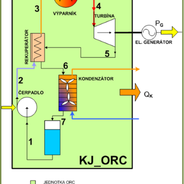
The principle of the ORC energy unit is the cycle of a steam engine, where the working substance is an organic medium that
receives heat from an external source into a closed loop. The device converts thermal energy into mechanical work, which can
be used to generate electricity or to drive other devices (eg cooling compressor). The working medium undergoes phase changes
during the cycle.
The most commonly used refrigerants as a working medium are those that allow the use of low-potential heat from any energy
source, both from the primary source and the waste heat. Then it is a renewable resource with zero emissions and universal
use.
The aim of our project is the development of a micro ORC cogeneration unit with an output of 1.5 and 5 kW.
Use of micro ORC units
In the case of micro cogeneration, these are outputs up to 50 kWe. The principle of cogeneration is the production of both
heat and electricity, both from primary and secondary sources. In the case of primary sources, it will allow us to cover local
electricity consumption, reduce transmission losses and allow us to operate in an independent island system. It is a highly
efficient process of using primary energy with an efficiency of up to 95%.
In the case of waste heat, it is possible to process residual heat from the flue gases of biomass boilers, process heat from
food, woodworking, glass and chemical plants or conventional combustion engines used to drive compressors or power plants.
Specifics of the proposed solution
The main criterion of our approach to the design of the micro cogeneration ORC unit was to achieve the highest possible efficiency
of the entire plant and low production costs for productive production. This results from the economic advantage of these
low-power energy equipment, where the return on investment is on the verge of profitability. So we needed to design a device
that was highly efficient to produce electricity and yet cheap.
The main components we focused on were the choice of the expander used and the choice of a suitable working medium.
The goal was to develop a micro cogeneration unit with an output of 1.5 and 5 kW.
Design and power parameters of the 1.5 kW unit:
| Parameter | Nominal value | Unit |
| Inlet pressure | 10.4 | bar |
| Inlet temperature | 100 | °C |
| Heat output of the source | 21 | kWt |
| Electrical power at terminals | 2,0 | kWe |
| Net electrical power | 1,5 | kWe |
| Inlet temperature of cooling water | 30 | °C |
| Outlet temperature of cooling water | 50 | °C |
| Usable heat | 18 | kWt |
| Total efficiency | 85 | % |
Micro turbine
A project to implement the ORC unit is currently underway, together with a 25 kW pellet boiler and battery storage. The ORC unit will supply 1.5 kWe of constant electrical power.
![[album/Products_Model_Product/76/Obrazek1(1).png]](https://www.techsim.cz/content/images/album/Products_Model_Product/76/Obrazek1(1).png)
The turbine shaft is connected to the generator or alternator gearbox by an electromagnetic clutch. The electromagnetic clutch contains a baffle that hermetically separates the refrigerant circuit from the environment and predestines the entire unit for automatic and maintenance-free operation. The ball bearings are lubricated with refrigerant and no service is required.
![[album/Products_Model_Product/76/Obrazek1(2).png]](https://www.techsim.cz/content/images/album/Products_Model_Product/76/Obrazek1(2).png)
Choosing the right refrigerant
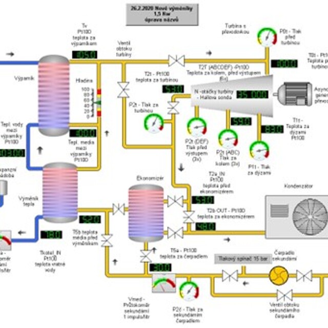
Description of the ORC unit test circuit
![[album/Products_Model_Product/76/Obrazek4.jpg]](https://www.techsim.cz/content/images/album/Products_Model_Product/76/Obrazek4.jpg)
The development of the entire ORC micro turbine unit with a generator was carried out with the consistent application of digital prototyping methods.
Input values for the design of the current part of the micro turbine:
| Parameter | Value | Unit |
| Working medium | R1233zd (E) | |
| Input temperature at the turbine casing inlet t0 | 100 | °C |
| Input pressure at the turbine casing inlet p0 | 10,42 | bar |
| Outlet pressure behind the turbine p2 | 1,3 | bar |
| Mass flow rate mT | 0,366 | kg.s-1 |
| Shaft speed nT | 35 000 | min-1 |
The complete flow design was performed using the STAR-CCM+ CFD system and the Simcenter HEEDS optimization engine using the Sherpa assistance system to select the most suitable combination of optimization methods.
![[album/Products_Model_Product/76/Obrazek1(4).png]](https://www.techsim.cz/content/images/album/Products_Model_Product/76/Obrazek1(4).png)
Furthermore, a static and dynamic inspection of the impeller and electromagnetic clutch was performed. The design of an electromagnetic
clutch for high operating speeds of up to 35,000 rpm proved to be critical during development. It was necessary to use high-strength
materials for the design of coupling bodies and special mounting of magnets, due to the high stresses from centrifugal forces.
All static calculations were performed using the FEA method in Simcenter 3D.
NX Nastran solvers were used to check the dynamics of the two impeller and clutch mass systems.
Prototype production
The production of the components of the ORC micro turbine unit was carried out with the consistent use of 3D printing methods
for the creation of working models of the unit and also the functional parts of the turbine housing molds. The flow parts
of the turbine were finally machined by 5-axis machining.
![[album/Products_Model_Product/76/Obrazek4(1).jpg]](https://www.techsim.cz/content/images/album/Products_Model_Product/76/Obrazek4(1).jpg)
Experimental measurements
The measurements took place in a test room, where a hot water electric boiler with an output of 18 kW was used as a source
of waste heat.
ORC micro turbine unit:
![[album/Products_Model_Product/76/Obrazek1(5).png]](https://www.techsim.cz/content/images/album/Products_Model_Product/76/Obrazek1(5).png)
Entire ORC unit:
![[album/Products_Model_Product/76/Obrazek4(4).jpg]](https://www.techsim.cz/content/images/album/Products_Model_Product/76/Obrazek4(4).jpg)
The prototype was each equipped with more than 30 measuring points for monitoring physical quantities such as pressures, temperatures,
turbine speeds, working medium flows, cooling water, levels in evaporators, etc. for connection to a central control system
(regulation, data acquisition). The ORC unit was completely developed, mostly manufactured in cooperation with MCAE Systems.
Circuit assembly, connection of pipes and filling with working substance (refrigerants R1233zd (E)) incl. The supply of the
measuring control panel and the connection of the sensors took place in cooperation with an external partner qualified to
work with refrigerants.
In order to measure the performance characteristics, MCAE Systems has also developed an electrical load (electricity consumer)
with proportional power control, which covers the required power range.

.png)
.jpg)
.png)

.png)
.png)
