Blog
Torsional vibration testing
The main trends in the development of powertrains (as well as other) systems are:
- increase efficiency,
- reduce emissions,
- and maintain performance.
The result of these trends is constant innovation and new technologies. Balancing NVH (noise and vibration) behavior against
performance and efficiency is a challenge that many development departments currently face. Having control of the powertrain
NVH is becoming increasingly challenging. How to avoid late control changes that affect NVH? The only solution is to go beyond
assessment of purely the powertrain NVH.
If you want to have control over NVH, it is necessary to combine separate measurement processes into a single and synchronized
measurement on the driveline test bench. This is a combination of these measurements:
- NVH assessment (orders, ODS, acoustic power,…)
- torsional vibration assessment (torsional resonance, drive performance, front-end accesory)
- sound source localization.
Today we look at torsional vibrations.
What are torsional vibrations?
For answering this question we can look at engine rotation speed (RPM) during a speed up from an engine. As you can see in
the figure below, RPM is not steadily increasing. Small fluctuations up/down occur.
.png)
Why and where do torsional vibrations occur?
We can take an example from an internal combustion engine. Internal combustion engines naturally generate very high torque
fluctuations as they go through a cyclic event (cylinder movement). And this results in a variable rotational speed = torsional
vibration.
Source of torsional vibrations could be e.g.
- clutch chatter = slipping in resonance with drivetrain
- clutch woop = engaging/disengaging low frequency pedal vibration
- front end accessory drive – transmission error, noise, belt resonances
- driveline torsional shaft resonances
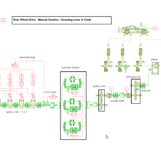
- gear-box – transmission error and variable load due to gear-mesh irregularities
- combustion engine – periodic irregulaar torque by nature, downsizing
- valvetrain
- turbocharger/supercharger – gas or fluid pressure pulsation
- torsional damper
Torsional vibrations do not occur independently. Torsional vibrations are only one aspect of dynamic behavior. Torsional and "other" vibration loads occur simultaneously. They affect durability, vibration, noise, comfort and performance. It must be taken into account that torsional vibrations cannot be measured by conventional translation sensors.
.png)
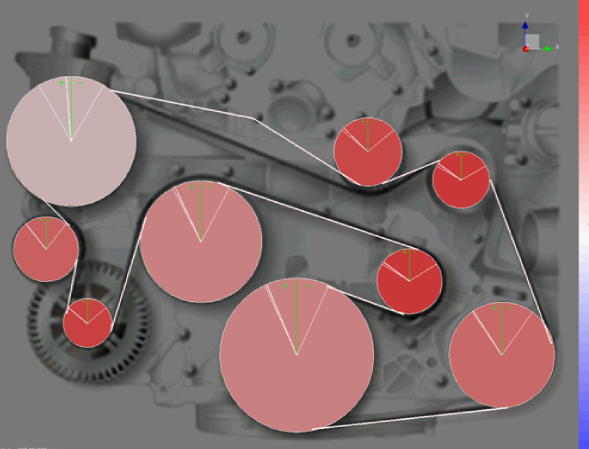
Why are torsional vibration important for NVH?
Torsional vibrations and NVH are connected. The explanation is clear - there is a direct link between the torsional vibrations of the drivetrain and the noise inside the car.
.png)
Torsional vibration testing
We can use a wide range of sensors and techniques to measure torsional vibrations. Let's focus on a few of them.
A) Direct measurement techniques
For direct measurement technique we use
- angular accelerometers,
- strain gauges,
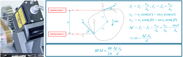
- dual-beam laser interferometers.
Angular accelerometers measure directly torsional vibration, have very good dynamic range and low sensitivity to translation vibrations (when 2 accelerometers are well aligned on diameter). Main disadvantages are mass loading on small shafts, risk of unbalance, telemetry or slip-rings requirement, no absolute angle (no angle domain), no TDC reference and risk of loosing equiment (centrifuge forces).
![[04(2).png]](https://www.techsim.cz/content/images/04(2).png)
Strain gauges measure directly torsional stress, have low sensitivity to translational vibrations and are useful for load and torque measurements. Main disadvantages are no rpm, no angle, telemetry or slip-rings requirement, mass loading on small shaft, risk of unbalance na TDC reference and also risk of loosing equipment due to centrifuge forces.
![[05(2).png]](https://www.techsim.cz/content/images/05(2).png)
Dual-beam laser interferometers have direct torsional vibration measurement, low sensitivity to translational vibrations and low sensitivity to shaft shape. There is only few disadvantages – no absolute angle and no angle domain, no TDS reference. The biggest disadvantage is a price.
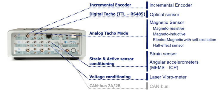
B) Coder based techniques
Coder based sensor are based on discrete angle position measurement. Multiple markers are available at fixed angular position of the shaft. Time at which the makers is passing in front of the sensor are measured. The resolution is determined by the number of markers. In this family of sensors we could mentioned:
- magnetic sensors on gear/fly-wheel teeth
- optical sensors
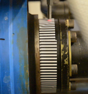
- zebra tapes & optical sensors
- incremental encoders
.png)
![[08.png]](https://www.techsim.cz/content/images/08.png)
![[09.png]](https://www.techsim.cz/content/images/09.png)
Optical sensors + zebra tape solve the problem with ambient light and it is only needed to be precise in how to fix the tape on the shaft.
![[10.png]](https://www.techsim.cz/content/images/10.png)
Incremental encoders are very convenient when the instrumentation can be part of the test bench. The advantages are accuracy and high number of pulses. Disadvantages are complex instrumentation and mass loading.
Encoder-based techniques have several rules that are good to consider if you choose this method of measuring torsional vibrations. These rules answer the common question "How many pulses per revolution should I measure?".
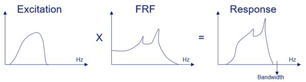
RULE 1: The bandwith of your assessed component
Any component or structure always has a certain bandwith. This is the frequency range in which it is sensitive to excitations. You are only interested to capture the torsional vibrations within the bandwith.
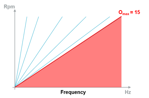
RULE 2: Make sure to select enough pulses per rev to capture all present torsional vibrations.
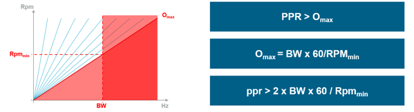
For torsional vibrations, thy NYQUIST criterium counts: PPR > Omax. That means that if we suppose 30 pulses per rev, I will only be able to capture torsional vibrations up to an order of 15. What happens of my real component has vibrations above 15? For example order 20? Order 20 cannot be measured with only 30 PPR ans even worse, this order will appear as order 10 in the measurement.
So what is the maximum of Omax? It is determined by bandwith and minimum RPM. Above the bandwith of structure, there are no torsional vibrations. So asses what is maximum possible order at minimum RPM of interest.
Which measuring set could be the right one for your torsional vibration problem?
- Simcenter Scadas & Torsional Vibration sensors - Simcenter Scadas support all types of sensors to measure torsional vibrations.
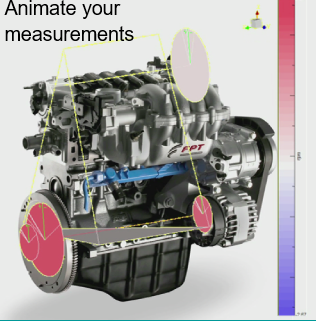
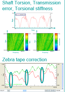
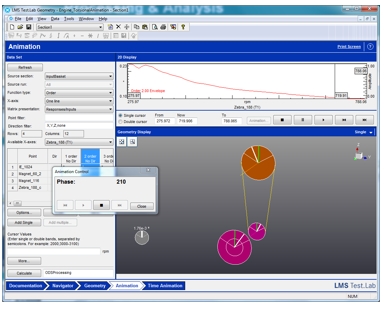
- Simcenter Testlab - Simcenter Testlab Signature Testing is complete processing solution (shaft torsion, transmission error, torsional stiffness, zebra tape correction), Simcenter Testlab ODS for torsional animation
- Simcenter Amesim - torsional simulation