Blog
Transfer path analysis - fundamentals
Qualifying and quantifying vibro-acoustictransfer paths
Transfer path analysis is a systematic approach to identify and assess structure-borne and airborne energy transfer routes from the excitation source to a given receiver location. TPA enables you to quantify the various sources and their paths, figure out which are important, which contribute to the noise issues and which ones cancel each other out.
The concept of the source-transfer-receiver approach is rather simple. Noise and vibration issues originate from a source.
This source transfers energy via one or more transfer paths that can be either structure-borne or airborne. Deciding whether
noise should be treated as structure or airborne is not as straightforward as it seems. The most appropriate way to objectively
describe both the sources as well as the transfer paths within a source-transfer-receiver model is TPA.
Essential keywords for TPA
it is important to understand the essential elements from the source-transfer-receiver model:
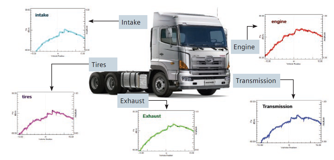
- The excitation sources: These can be structure and/or airborne, acoustical or vibration. Typical sources for a vehicle include the vibration of the engine, intake noise, tailpipe noise, road-induced vibrations, or radiated noise from vibrating panels.
- The transfer paths: Structural transfer paths are represented by the physical mounts and rigid connections, by which the noise and vibration are transferred from the source to the target location. Examples of airborne transfer paths are vibrating panels, intake or exhaust nozzles.
- The receiver locations: These are typically acoustical, such as the acoustic pressure perceived by the passengers in a vehicle during engine runup. It can also be vibrations in the steering wheel or seat rails, the noise perceived by the user of a household machine, or the vibration of a space station caused by an instrument in operation on the carrier platform
How TPA works?
The procedure to build a conventional TPA model consists of two steps:
- Identify operational loads from in-operation tests (for example, runup, rundown) on the road or on a chassis dyno.
- Estimate the frequency response functions (FRF) between the load interfaces and target locations.
.png)
What is typical application for TPA
TPA is a powerful tool that can be applied at several stages of development. It gives complete insight into NVH behavior and
leads to faster troubleshooting, better product refinement and a more methodical approach to vibro-acoustic design.
TPA can be applied to solve vibro-acoustics issues in a variety of large and small mechanical machinery, including: automative,
ships, wind turbines, motorcycles, trains, compressors, large engines and even full aircraft. TPA methods have been applied
to reduce sound power levels in printers and copiers as well as household appliances, such as refrigerators, washing machines
and dishwashers.
Main usage of TPA is:
- Vehicle development
- Pass-by noise engineering
- Troubleshooting - TPA was traditionally applied in the domain of troubleshooting NVH problems. The contribution of TPA in this regard remains vital.
Read more.