Blog
Electric Traction Motor Design Solutions
Key trends in electric vehicles show that native electric vehicle platforms could be the future of mobility. However, the
success of an electric car for the mass market will depend on its ability to penetrate lower-priced segments. Electric drive
and battery are one of the main factors influencing costs.
Today we look at the lightening of traction motors.
If the engine is not properly designed, its reliability is affected, which in the extreme case will lead to recall - it
will affect the brand name, price and related costs of product recall. One of the main problems with motors is the cyclic
loading of the motor, which naturally reduces its service life. Electromagnetic and thermal cycling occurs during acceleration
and braking due to high heat losses in a short time. This can lead to reduced reliability, especially if cooling is insufficient.
So how can we ensure the availability and reliability of traction motors while increasing their power density?
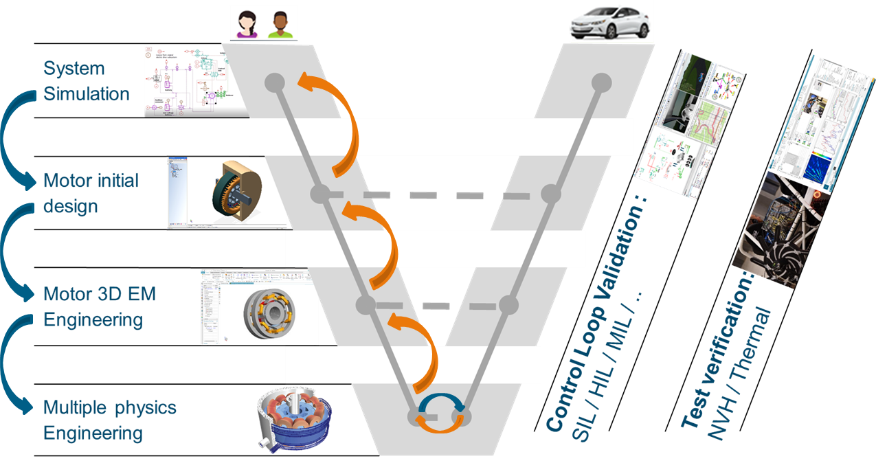
The power of simulations can currently be used to achieve this goal:
- System simulations are used to define the operating envelope of the traction motor under real vehicle operating conditions.
- Quick motor simulations are used to find an initial design that meets FEA-based electromagnetic and thermal performance.
- The final detailed design is then used to ensure that the motor meets the electromagnetic and design characteristics, is compliant with NVH and the cooling system. It is optimized to be effective in extreme operating conditions.
- Virtual and physical tests are then used to validate performance.
.png)
Initial motor concept
The initial search for the engine design should be within the limits set at system level in terms of performance based on
electro-magnetic-thermal analysis. The initial design also allows for design decisions such as engine topology, system-level
mechatronic analysis and vibroacoustic performance, thermal and energy management. The model is then used as a practical basis
for optimization, exported as a 1D model for system-level analysis and converted to a 2 or 3D model for more detailed analysis.
.png)
Simcenter MotorSolve automates a template-based interface for global model setup, saving time. Rotor and stator geometries can be easily defined
from editable templates or imported as custom DXF files. The winding is automatically generated with provisions for the inverter,
slots, wire sizing and other parameters for real motor analysis. The cooling system is then specified in terms of type, ie
non-ventilated, forced, sprayed and in terms of flow and inlet temperature. Thermal and EM (electromagnetic) materials are
then assigned. Materials are pre-sorted by engine parts for quick assignment. It is also important to ensure that the engine
meets the required peak torque and torque and speed operating envelope with associated efficiency. Furthermore, the effects
of the inverter or power supply can be analyzed. During the specified driving cycle, the temperature development in different
parts of the engine is analyzed. 3D temperature field analysis for hot spots ensures that magnets and end windings are within
the permitted temperature limits. During the specified driving cycle, the temperature development in different parts of the
engine is analyzed. 3D temperature field analysis for hot spots ensures that magnets and end windings are within the permitted
temperature limits. The effective use of core materials is evaluated by calculating local magnetic fields at full load. Finally,
the analysis can be easily shared using a report, which can include engine geometry, specification and performance analysis,
among other parameters.
The 1D model can then be exported to Simcenter Amesim for system mechatronic analysis. In this case, you can make sure that the engine meets
the vehicle's torque requirements. The model can also be exported to Simcenter Flomaster for energy and heat balance analysis. In this case,
the effect of the motor on the system at different cooling configurations for a given drive cycle is analyzed. Export support
at the 1D system level ensures that the original engine design meets system requirements.
.png)
A quick motor analysis will therefore help us arrive at a practical initial motor concept that meets EM and thermal requirements
while reducing system integration risks.
Detailed motor design
In the detailed engine design we can consider:
- extreme operating conditions,
- the importance of critical effects,
- analysis based on available materials
- manufacturability.
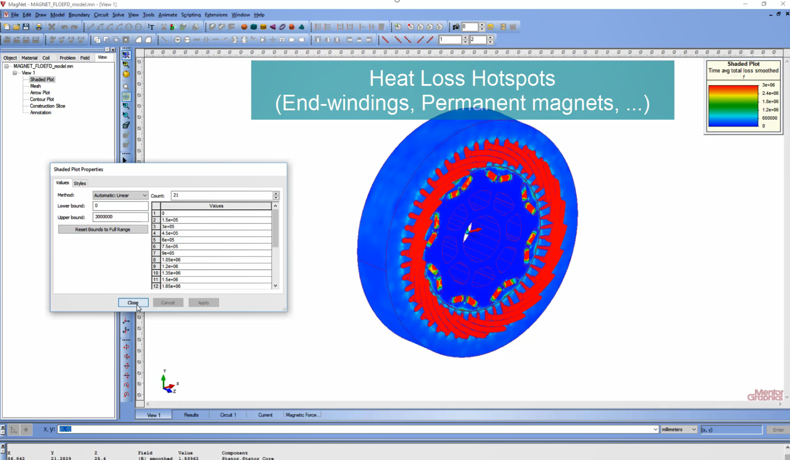
Detailed 3D analysis of the EM engine, which is necessary to generate accurate EM heat sources, taking into account the 3D
final effects, which are neglected or approximated in 2D or 2.5D analysis. The Simcenter Magnet 3D engine model generates accurate EM heat
losses by incorporating end effects. The model has assigned real materials, then the properties of permanent magnets are defined.
The coils and circuit are set to power the windings. The mesh (discretization) in the air gap, which is a critical area in
the engine, is controlled to prevent excessive refinement, which saves computation time. The rotational movement of the rotor
and the parameters of the transient analysis can be set. In the performance analysis, we check the effective use of the core
material by magnetic load analysis. We must also ensure that the magnets are not demagnetized under this load. It is also
possible to assess the electromagnetic heat losses due to the 3D end effects on the magnets and end windings.
.png)
The detailed design is more realistic because its analysis is based on a more accurate model using available materials within
production constraints and its EM performance should be ensured under extreme operating conditions.
Virtual motor verification
The detailed design is then virtually verified to ensure it meets the electromagnetic, thermal and mechanical constraints.
The operating condition of the engine, which depends on the operating temperature, must be verified for extreme conditions
and must also be mitigated against risks that may affect its service life.
CFD motor cooling optimization could be done to ensure that it is within magnets and thermal insulation. It is possible to
import geometry from Simcenter Magnet to Siemens NX. Simcenter FLOEFD can then also be used directly in Catia V5, PTC Creo and Solid Edge.
.png)
The results of the thermal analysis, which were obtained from the previous electromagnetic simulation in Simcenter MAGNET, are applied to
the corresponding components. The main goal of the analysis is to calculate the winding temperature and pressure drop. The
overall functionality of the motor, which depends on its insulation and the temperature limits of the magnets, must be verified
to ensure its operation under all foreseeable conditions and to guarantee its service life.
.png)